SunVena Solar Blog
Residential Solar News, Insights & Resources
Top 10 Solar Inverter Installation Mistakes to Avoid
A reliable solar inverter installation begins long before the inverter reaches the wall. It starts with accurate site measurements, a clear electrical design, and respect for the manufacturer’s instructions. Small oversights can create large problems. Loose terminals may cause heat. Poor ventilation can shorten equipment life. Incorrect voltage readings can damage components before commissioning begins.
Bill Brooks, PE, a respected solar PV engineer and educator, has said, “The inverter is the heart of the PV system.” That practical comparison matters. The inverter manages energy conversion, system protection, monitoring, and grid interaction. Treating it like a simple box can lead to expensive mistakes. A professional installer checks string voltage, polarity, grounding, cable routes, clearances, and shutdown procedures. They also document each test instead of trusting assumptions.
This guide examines ten common solar inverter installation mistakes and explains how to avoid them. Expect details that matter on site: a shaded inverter behind a storage rack, a cable bent too tightly, or a connection tightened without a torque wrench. These errors are easy to overlook. They are not always dramatic at first.
Perfect installations are rare. Even experienced teams can miss a detail under time pressure. That is worth admitting. Careful review remains essential. Local electrical requirements, utility rules, and product manuals must guide every project. The safest approach combines field experience, verified measurements, qualified supervision, and honest documentation. A successful installation should operate quietly, safely, and predictably for many years.
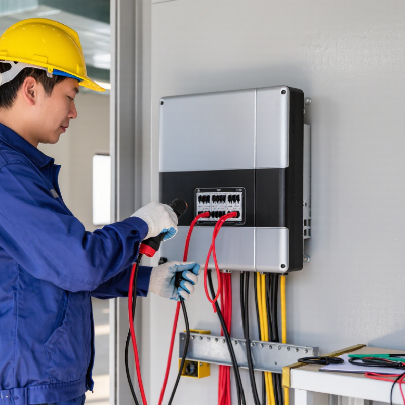
Planning and Site Assessment Errors Before Solar Inverter Installation
Top 10 Solar Inverter Installation Mistakes to Avoid
Planning failures often begin before equipment arrives. A clean-looking roof can still be a poor electrical site. Inspect roof age, structural capacity, drainage, and fire-access paths. Do not measure shade only at noon. Morning and winter shadows can change production significantly. IEA PVPS reported more than 400 GW of solar capacity additions in 2023. Small planning errors now affect increasingly valuable systems.
Inverter placement also needs careful thought. Avoid hot attic corners, damp walls, direct rain, and areas with poor airflow. Check service clearance, cable routes, voltage, phase configuration, and grounding requirements. NREL’s PVWatts documentation models shading, temperature, wiring, and inverter losses separately. That matters. A field plan that ignores these losses may look efficient on paper but perform poorly later. Even experienced teams can miss future battery space or electrical-panel capacity.
Tips: Use a site-survey checklist with photographs. Record shade at several times and seasons. Confirm utility requirements before selecting the inverter. Test signal strength where monitoring equipment will operate. Leave practical room for maintenance. Recheck the roof after heavy weather. This step feels repetitive, but skipping it can create expensive redesigns.
Top 10 Solar Inverter Installation Mistakes to Avoid - Planning and Site Assessment Errors Before Solar Inverter Installation
| No. | Planning or Assessment Mistake | Why It Matters | Recommended Assessment | Installation Risk | Verification Before Installation |
|---|---|---|---|---|---|
| 1 | Ignoring shading and obstruction patterns | Shade from trees, chimneys, parapets, or nearby buildings can reduce solar production and may affect module-level operating conditions. | Survey shading throughout the year, not only at the time of the site visit. Record obstruction height, direction, seasonal changes, and the affected array area. | Lower energy yield, inaccurate production estimates, and poor string layout. | Complete a shade analysis and revise the array layout or equipment design where persistent shading is present. |
| 2 | Selecting the array orientation and tilt without site analysis | Azimuth, roof pitch, and seasonal solar position influence annual irradiance and the timing of energy production. | Measure roof azimuth and pitch, identify east-, west-, and south-facing surfaces where applicable, and compare the layout with the project’s energy profile. | Unnecessary production losses and mismatched generation during periods of high electricity use. | Document compass direction, roof slope, usable roof planes, and any design trade-offs before selecting inverter capacity. |
| 3 | Failing to inspect roof condition and remaining service life | Solar equipment can remain in service for many years. Installing on a roof requiring early replacement may create costly removal and reinstallation work. | Inspect roofing material, age, leaks, penetrations, drainage, flashing, and maintenance history. Repair or replace unsuitable roofing first. | Water intrusion, structural damage, warranty disputes, and avoidable reinstallation costs. | Obtain a documented roof assessment and confirm that attachment details are compatible with the roof construction. |
| 4 | Overlooking structural loading and wind or snow exposure | Modules, racking, ballast, and wind uplift impose additional loads. Local snow, wind, seismic, and roof construction conditions affect attachment requirements. | Verify roof framing, allowable loads, attachment locations, ballast limits, wind zones, snow loads, and applicable structural requirements. | Roof deformation, attachment failure, leaks, or unsafe operation during severe weather. | Obtain structural calculations or approval from a qualified professional when required by the project or local authority. |
| 5 | Choosing inverter size without a complete load and generation study | Inverter sizing must reflect array power, expected irradiance, temperature, clipping strategy, energy goals, and future expansion plans. | Compare the array’s DC rating with the inverter’s allowable DC input, AC output, MPPT operating range, maximum current, and expected operating temperatures. | Excessive clipping, underused capacity, nuisance shutdowns, or an unsuitable design for future loads. | Review a site-specific production model and confirm all electrical ratings under the project’s minimum and maximum temperature conditions. |
| 6 | Not checking the electrical service and interconnection capacity | The service rating, panel capacity, busbar limitations, utility requirements, and point of connection determine whether the proposed system can be connected safely. | Review the main service rating, panelboard rating, available breaker spaces, load calculation, existing generation, utility rules, and required disconnects. | Permit rejection, redesign, overloaded equipment, or unsafe backfeed conditions. | Complete the electrical load and interconnection review before ordering equipment or finalizing the single-line diagram. |
| 7 | Ignoring voltage and current changes caused by temperature | PV voltage generally rises in cold conditions and falls in hot conditions. Array current and inverter input limits must remain within their permitted ranges. | Calculate maximum string voltage at the lowest design temperature and operating voltage at high temperature. Check short-circuit and operating current against inverter limits. | Inverter damage, startup failure, overvoltage trips, or reduced performance during hot weather. | Use module electrical coefficients, local design temperatures, and the applicable electrical code during string design. |
| 8 | Mixing different roof planes or module conditions on one MPPT | Modules with different orientations, tilts, shading patterns, or electrical characteristics may operate at different maximum-power points. | Group modules with similar azimuth, tilt, irradiance, and electrical characteristics. Use separate MPPT inputs or another suitable design when conditions differ. | Mismatch losses, unstable tracking, and lower energy harvest. | Prepare a string map showing module count, roof plane, orientation, shading exposure, and MPPT assignment. |
| 9 | Planning inverter location without considering environment and access | Heat, moisture, dust, corrosive air, direct sunlight, flooding, and inadequate clearance can shorten equipment life or cause thermal derating. | Evaluate ambient temperature, ventilation, weather exposure, flood risk, corrosive conditions, service clearances, cable routes, and emergency access. | Overheating, derating, corrosion, difficult maintenance, and premature failure. | Confirm the proposed location meets the equipment installation instructions, local code, environmental rating, and clearance requirements. |
| 10 | Skipping permits, utility coordination, and code review | Solar installations commonly require building, electrical, fire-safety, and utility approvals. Requirements vary by location and system type. | Identify the authority having jurisdiction, utility interconnection process, inspection stages, labeling rules, rapid-shutdown requirements where applicable, and emergency access provisions. | Construction delays, failed inspections, forced modifications, and delayed permission to operate. | Secure approved drawings, permits, utility documentation, and inspection requirements before installation begins. |
Assessment principle: Final inverter selection and installation should be based on site-specific measurements, equipment ratings, structural review, electrical calculations, manufacturer instructions, and the requirements of the applicable authority having jurisdiction.
Related Posts
-
Unleashing the Power of Solar River Inverters for Sustainable Energy Solutions
-
Top 10 Best 3 Phase Solar Inverters in 2026?
-
Navigating Import and Export Certifications for Best on Grid Solar Inverters in the Global Market
-
10 Essential Tips for Choosing the Right 3 Phase Solar Inverter for Your Home
-
How to Choose the Best Solar Power Inverter for Your Needs?
-

China Top 10 Solar River Inverter Suppliers?